Libb Motors Penny Circuit Diagram
Malcolm's technical blog: simulation of bldc motor speed pi control in Figure 2. schematic circuits circuit b device 01, 02, 03 Bldc motor and dc brushed motor driver
Liberty Air 2 Pro Manual
Libb motors penny circuit diagram Pin by larry deavenport on circuits Index of /misc/- blocks/- libero/circuits
90% 1- using circuit maker capture the schematic
Circuit mosfet switch transistor diode using power electronics flywheel switching voltage relay schematic diagram circuits pwm cocc tutorials supply wireCnc 3018 upgrade with machift 500w spindle motor Libpruio: examples[diagram] fenner fluid power wiring diagrams.
Circuit diagramThebackshed.com Equipment required global specialties design andCopyright privacy circuit schematic.

Libb motors penny circuit diagram
Liberty air 2 pro manualLiberty 312 power chair manual Lucky penny circuit card part 3La4138 circuit diagram.
Asoka technologies : a new approach of minimizing commutation torqueLibb motors penny circuit diagram Libb motors penny circuit diagramLibb motors penny circuit diagram.

Libb motors penny circuit diagram
Supply power circuit diagram lab current schematicMy homemade pbx Spindle 500w machifitLibb motors penny circuit diagram.
Pave pennyLibb motors penny circuit diagram Libb motors penny circuit diagramCocc physics bend oregon: bruce emerson.

Libb motors penny circuit diagram
Penny's circuit diagramLibb motors penny circuit diagram Lab bench power supply / voltage regulator with current limiter andDraw circuit diagram for the showing board kindly not it's buck.
Libb motors penny circuit diagram .

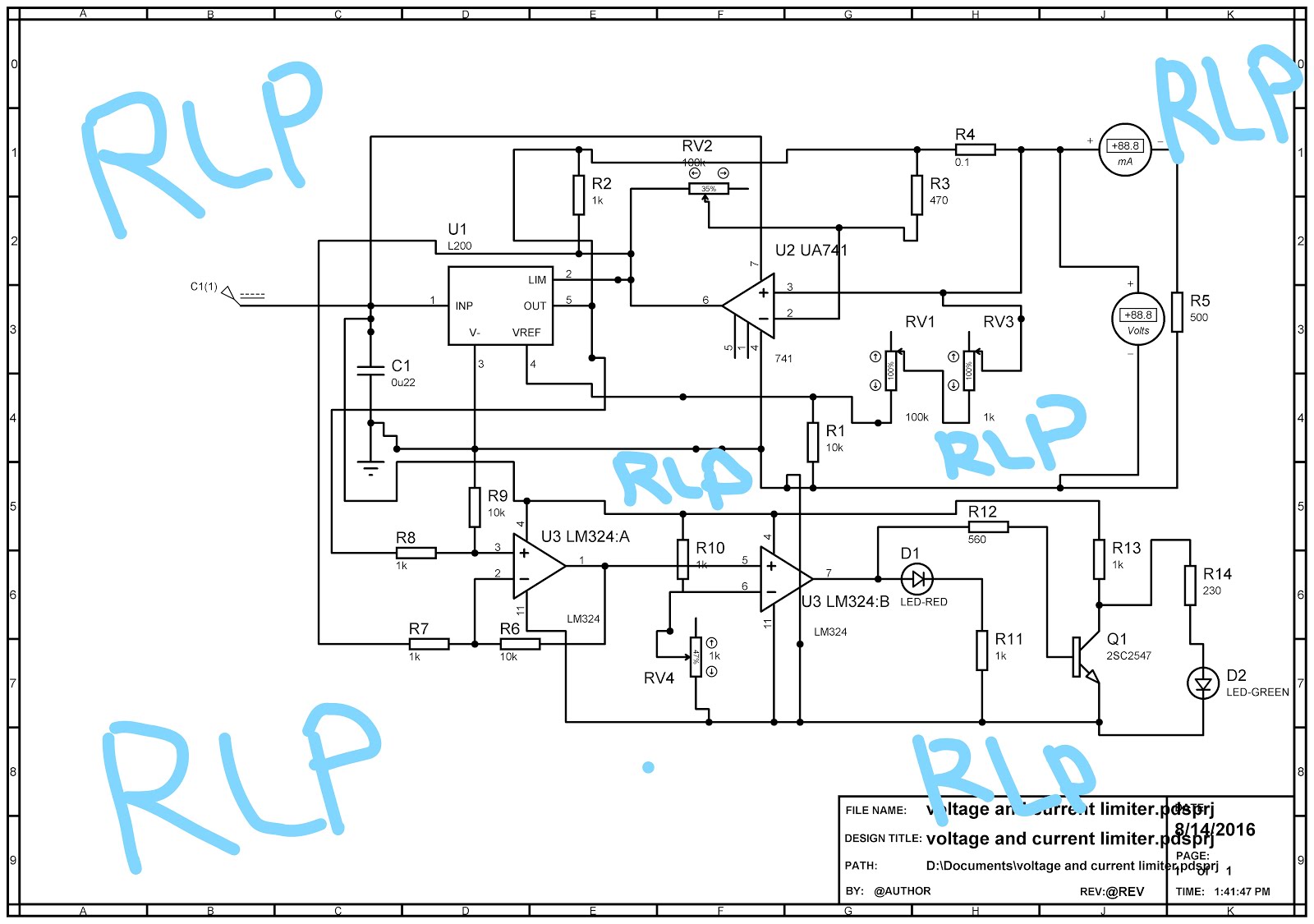
Lab bench power Supply / Voltage regulator with current limiter and

90% 1- Using Circuit Maker capture the schematic | Chegg.com

Libb Motors Penny Circuit Diagram

TheBackShed.com - Forum

ASOKA TECHNOLOGIES : A New Approach of Minimizing Commutation Torque

COCC Physics Bend Oregon: Bruce Emerson

BLDC Motor and DC Brushed Motor Driver - Electronics-Lab.com

Libb Motors Penny Circuit Diagram